
LIVE OPERATOR’S MANUAL
Flash Cannon G400 Series Air Cannons
Installation, operation, and maintenance — everything in the printed manual, alive on one page. Built for high-temperature applications up to 400°F, on kilns running as hot as 2,000°F.
↓ Download the PDF Manual Talk to a Cannon Tech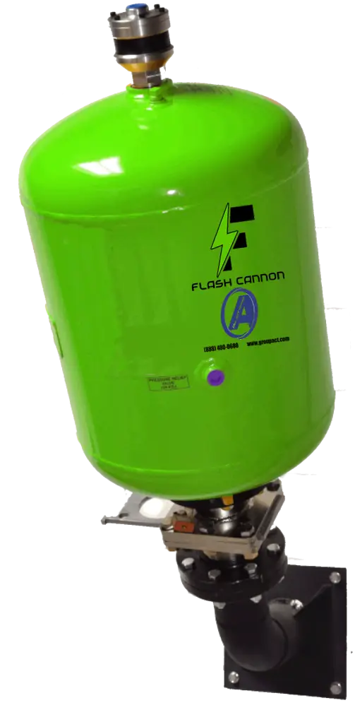
The G400 Series Lineup
Four models, one job: restore material flow with a sudden, high-energy blast of stored compressed air.
| Model | Part # | Discharge | Tank | Volume |
|---|---|---|---|---|
| G400-40-50 | #814100 | 4” | 12” × 28” | 50 L (1.7 ft³) |
| G400-40-150 | #814300 | 4” | 20” × 30” | 150 L (5.0 ft³) |
| G400-60-300 | #817400 | 6” | 24” × 48” | 300 L (10.6 ft³) |
| G400-60-650 | #817500 | 6” | 30” × 60” | 650 L (22.8 ft³) |
What It Does
The Flash Cannon is a direct-blast aerator: a compressed air reservoir with a quick-opening valve that releases stored air in one sudden blast, directed through a discharge pipe to break up material that is bridging, arching, rat-holing, or clinging in silos, hoppers, chutes, and storage piles. The direct-blast design lets air escape straight into the discharge pipe with no bends or obstructions — the faster the discharge, the greater the force, the more material moved. Where vibration is impractical (concrete bunkers, ground piles, cohesive materials like wood chips), the cannon is the answer.
⚠ Safety First
DANGER
Never stand in front of an Air Cannon during discharge — the blast exceeds 1,000 ft/sec and 1,500 lbs of force and can cause serious injury. Never use an Air Cannon to shoot a projectile.
WARNING
- Pressure vessels are ASME code welded and certified — never weld onto the tank.
- Cannons must be empty of air when transported, mounted, or inspected.
- Never discharge a cannon that is not securely mounted — recoil is severe. Mount on Schedule 40 pipe or equivalent, with a safety cable from the tank ring to structural support.
- Never enter a bin or hopper while cannons are pressurized.
- Follow all OSHA, ANSI, and site safety procedures.
CAUTION
G400 cannons withstand ambient temperatures to 400°F — beyond that the piston will seize (not covered by warranty). On 2,000°F kilns, use a discharge pipe at least 36” long with one long-radius bend. Vent closed storage vessels if firing pressure exceeds 0.5 psi inside.
How It Fires — The 8-Step Cycle
- A 3-way normally-open valve admits plant air; pressure seals the piston against the seat.
- Plant air passes the check valve in the valve cap and fills the pressure vessel.
- The cannon sits charged on standby, ready to fire.
- Switching the 3-way valve exhausts the fill line — pressure behind the piston drops.
- Tank pressure forces the piston back to the open position.
- Stored air escapes through the discharge in an explosive blast, lifting and separating material.
- Re-switching the valve restores plant air and recharges the cannon.
- Plant air pressure re-seats the piston, sealing out contaminants.
Air Requirements at a Glance
- Operating pressure: 45–125 psi filtered, regulated air (80–100 psi is the sweet spot).
- Filtration: 40-micron filtered air only.
- Lubrication: none required — ever.
- Relief: tank carries a 125 psi pressure relief valve; it can also fully exhaust the tank without firing.
- Nitrogen, CO₂, or other inert gas can substitute for plant air.
Manual or Automatic Control
Manual: a 3/4” 3-way normally-open manual valve — open to fill and stand by, closed to fire, back open to refill. Automatic: a 3/4” normally-open solenoid driven by a Flash Master Blaster sequencing timer (or momentary switch); energizing the solenoid fires the cannon, de-energizing refills it. Thanks to the factory-mounted G-Series Quick Exhaust Valve, the control valve can sit up to 100 feet from the cannon with zero loss of blast force.
Required Accessories & Replacement Parts
Every component below is available from ACT — add them to a quote and we’ll price the full system. (Direct product links are coming to this page as we add each part to the store.)
- Shut-off ball valve — isolates the system from plant air; 1/2”+ recommended, one per FRG.
- Filter-Regulator-Gauge (FRG) — filters and regulates supply; drain daily; one per four cannons.
- Airline check valve — prevents accidental firing on supply-pressure loss; one per cannon.
- 3-way control valve (manual or solenoid, 3/4”) — the trigger.
- G-Series Quick Exhaust Valve — factory-mounted, patent-pending, spring-free immediate closure.
- Mount & discharge assemblies — 4” #850040 / 6” #850060
- High-temp diffusion nozzles (1650–2100°F) #860040 / #860049
- Safety cable kit #169014
- Master Blaster timer TMB-108 (8 circuits, 110V) #891008.
Start-Up in 10 Steps
- Secure every connection — cannons, discharge assemblies, air and electrical.
- Confirm all 3-way control valves are open.
- Set the FRG to minimum pressure.
- Open the shut-off ball valve to admit plant air.
- Set the FRG to charging pressure — minimum 40 psi, maximum 125 psi, 80–100 psi for most work.
- Check every airline connection for leaks; mark any found and depressurize.
- Repair leaks and repeat from step 3. Clean? Continue.
- Test-fire each cannon individually (manual lever, or solenoid via switch/timer manual mode).
- Configuring a sequencing timer? Set firing order, time between blasts, and time between cycles per the timer manual.
- System is ready for service.
Test firing before first mounting: lay the cannon on its side, support it against recoil, relief valve in place, 45–60 psi only, eye and ear protection on, everyone clear of the discharge.
Maintenance — What Actually Needs Doing
- Quick Exhaust Valve bands: replace every 50,000 blasts or annually. Two bands, always — if “Replace Bands Now!” is visible, the outer band is gone; replace immediately.
- FRG: drain the filter reservoir daily; wash with warm soapy water as needed; 40-micron replacement elements.
- Mounts: must stay rigid — check and retighten periodically; repair or replace rusted parts.
- Internal valve: designed for years of maintenance-free service; inspect on a rotating semi-annual/annual schedule in harsh environments.
- Before ANY service: shut off air, fire the cannon or pull the relief-valve ring until the tank is fully empty. An unrelieved tank can discharge unexpectedly — this can be fatal.
Troubleshooting: Weak or No Blast
| Probable cause | Fix |
|---|---|
| Leaks or worn control / quick-exhaust valve | Inspect for wear, damage, contamination; repair and leak-check the system |
| Control valve too far away or undersized | Keep within 100 ft with the QEV (10 ft without); use recommended sizes |
| Piston lodged by contamination | Disassemble and clean the valve; check the filter element |
| Low air pressure or incomplete fill | Raise regulator setting; allow more fill time; use a larger fill line |
| Sharp bends or blocked discharge pipe | Use long-radius elbows; clean and reposition the pipe |
| Piston seized by heat >400°F | Lengthen discharge pipe and add a long-radius bend |
| Firing into empty space | Reposition discharge above the material blockage |
Full troubleshooting, dimensions, plumbing diagrams, performance data, and parts drawings live in the PDF appendices.
TAKE IT WITH YOU
The complete manual — every appendix, diagram, and part drawing
↓ Download the Operator’s Manual (PDF) Explore Air CannonsQuestions on your install? Call (909) 350-4703 — or ask about our Air Cannon Exchange program.
The ACT Group
Applied Conveyor Technology — bulk material handling experts. Dust control, conveyor services, silo cleaning, parts, and engineering.
909-350-4703
888-480-0680 (toll-free)
© 2026 The ACT Group (Applied Conveyor Technology). All rights reserved.
Service Areas
Silo Cleaning: Inland Empire · Los Angeles · Nevada
Dust Collection: Inland Empire · Los Angeles
Belt Vulcanizing: Los Angeles · Nevada